Saturday, June 7, 2008

suspention assembled.....

Finally got around to buying some POR-15. This stuff is great! It's like the poor man's powder coat! It is very toxic and I was told to use a mask, gloves etc...It dries to a hard finish and make sure to put a piece of plastic when you close the can or the paint will be weld the can shut! Don't get this paint on your skin you will have a hell of a time getting it off!
It brushes on and then melts so you can't see any brush strokes. I will be painting the engine bay with this.....


I decided to bolt everything up so I can put the car on the ground and rolling so I could take it to my friends shop to start working on the cage.....he has a notcher there so I will be fitting and tacking everything in there then bringing it back to do final welding here in the garage. I don't have a floor mount drill press here so It's easier just to do all the tube cutting/ffitting and tacking there then bring it back.....

Used new SKF bearings packed them up with lots of Mobil1 sythetic bearing grease......

Assembled adjuster with Ireland poly bushings.....

completed rear assembly
bolted on subframe
New Myle ball joints
new tie and center rods
bolted on vented rotor
All done and ready to roll! Rolling chassis Time.....

Sunday, May 18, 2008

Hot sunday in the valley....

My moms garage is in the valley and boy was it a sauna in there.....! I managed to get alot done and only sweat out a few buckets!

I finish grinding off all the 5 layers of paint in the engine bay and frame rails. Luckily no serious rust to report....

So now I'm ready to start on the cage work....
you might notice I cut out the passenger firewall "foot bulge". This is to make it easier to install and removal the headers....might seam silly but why not! I like making my life easier...

Also finally finished welding on the subframe adjusters. Then I used the air grinder to finish cutting out the adjustment slots. The "eccentrics" required some grinding filing to ensure proper smooth operation....basically it all took some fine tunning to get just right.....

Not bad eh? I'm pretty proud of myself.

Completed subframe
Outermost pickup point adjust toe and inside (vertical slots) adjusts camber.

Completed modified rear suspension!

Reinforced trailing arms and now adjustable subframe ! (also solid subframe mount bushing not pictured)

Monday, May 12, 2008

Truck? I don't need no stinking truck!

Mother's day weekend started by going to pickup some 1.5" x .095 DOM tubing for the roll cage modifications.

the workers at the metal yard looked at me funny when I pointed to my lowered M3 and said "put it on the roof!"

They were like are you sure? It's 60 odd pounds of tubing that 20ft. long!

I told'em....."It's okay this is how we do it in Brazil all the time!" they all had a laugh...
I didn't break any speed limits but I got home just fine....

According to my receipt I got 2 pieces 18'.3" long. = $35.59 each ! I believe that is a smoking deal!

The M3 makes a great hauler......

Alot of time was spent talking and discussing about the engine bay cage design......

In my previous post you saw my version 1.0........I'm calling this V.2.0

Soon into discussion we realized we needed to have the engine in place with the head and most importantly the DISTRIBUTOR......


Within 15 mins we had it all together.....here is version 2.0
The Engine bay tubes will be 1"-1/4" x .120 wall
This design clears the distributor, the carburator etc.... The green things are "taco" gussets with dimple dies.....
after pretty much setteling with this design....I continued my work with the subframe adjusters..... Make sure everything is clean and secure before welding
Measure with calipers to insure that both plates are in exactly the same place. BEFORE welding

Then the fun part..... weld away!

Tuesday, May 6, 2008

Bimmerfest recovery....back to work!

I was working the Stealthauto booth at Bimmerfest this weekend and unfortunately did not get a good chance to look around.

I did stop by the Ireland Engineering booth and picked up some camber and toe rear adjustable weld on kit.

SO back home on Sunday I got back to work on the car abit....

Here is the Camber kit

First I clamped a piece of flat stock to serve as a backer so I may take my big F'ing hammer and make the small turned out lips flat.
Marking where to cut so that with the plate on now we have a slot so the eccentric adjuster may move back and forth....
On the Semi-trailing arm design of the 2002 (also e30 and Mcoupe). The more you lower the car or basically move th arm further up into it's travel, you gain toe-in and the tire gains negative camber. So usually a 2002 at race ride height will have too much camber and too much toe-in. This kit will allow you to dial some of that out.

Also if you ever plan on running bias ply slicks, you will want close to 0 camber so these become even more important.

Toe will move back and forth on the outermost trailing arm mount on a horizontal plane. This will give you the ability to adjust toe.

The innermost trailing arm mount (closest to the diff) will be cut so we may move the arm on a vertical plane. As we move the eccentric down we get more negative camber and more we move it up we reduce the amount of negative camber.
My first TIG weld on the adjustment plates

Wednesday, April 30, 2008

Paintball or work?


Took a break and went paint balling on Saturday but at least got some work in this weekend....

finished removing all the paint from both inside fenders....and welding all the small holes that were drilled to mount various items in the last 30 odd years of ownership.....
did some seam welding.... fender to firewall
I'm taking my inspiration for my "engine bay cage" from one of the cars from the guys from http://www.skidmarkracing.net

here is his tube design/engine bay

Here is my version of his concept....Im calling this Version 1.0

I did not like the way he just "seamwelded" the tubing to the 'shock tower'. I thought I could improve on his idea. This is and old car running really STIFF springs supported by 39 year old spot welds and rusty sheetmetal.

So I decided to construct a 'strut tower' reinforcement box.

Both to strengthen the strut mounting area and to transfer some of the load into the roll cage.

My racing rules state I cannot alter the suspension mounting points. There fore my strut holes are in the same place and I'm not moving the strut mounting point inward like I would like to (to gain more camber). I also would like to raise the strut tower abit to gain suspension travel. But that is also prohibited.

So it is merely a mounting point for the tubes and a reinforcement for the area.came up with this strut tower reinforcement "box"
more detailed view of the reinforcement box/tube mounting... the black circle represents where the tube will be welded to the 'box'
A side view of the design. The most forward tube will reach down and be welded to the frame rail. The 2 triangulated tubes will reach thru the dash and attach to the top dash tube.
I will also weld a "taco gusset" with a nice dimple die to this connection.

Monday, April 21, 2008

Cage modifications started!

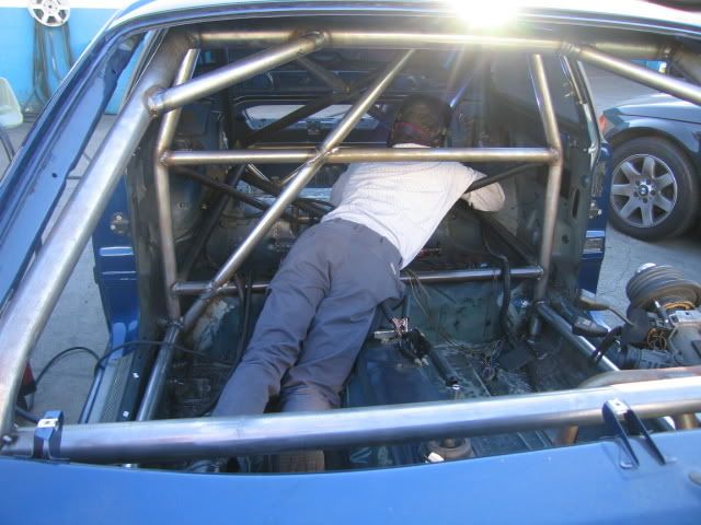
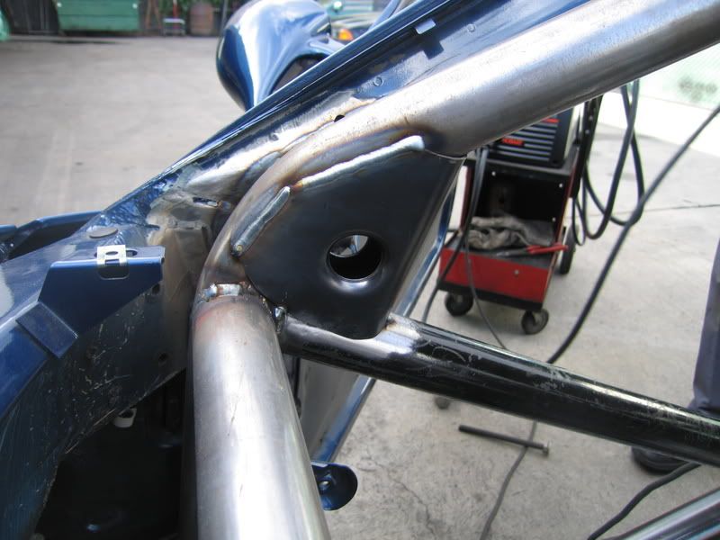
We finally finished my friend Dimitri's '95 M3 NASA TT car. We put quite an extensive cage in it. I think he will put up a Project thread here in a few days.

here's a few pics!


here a video of the completed car...
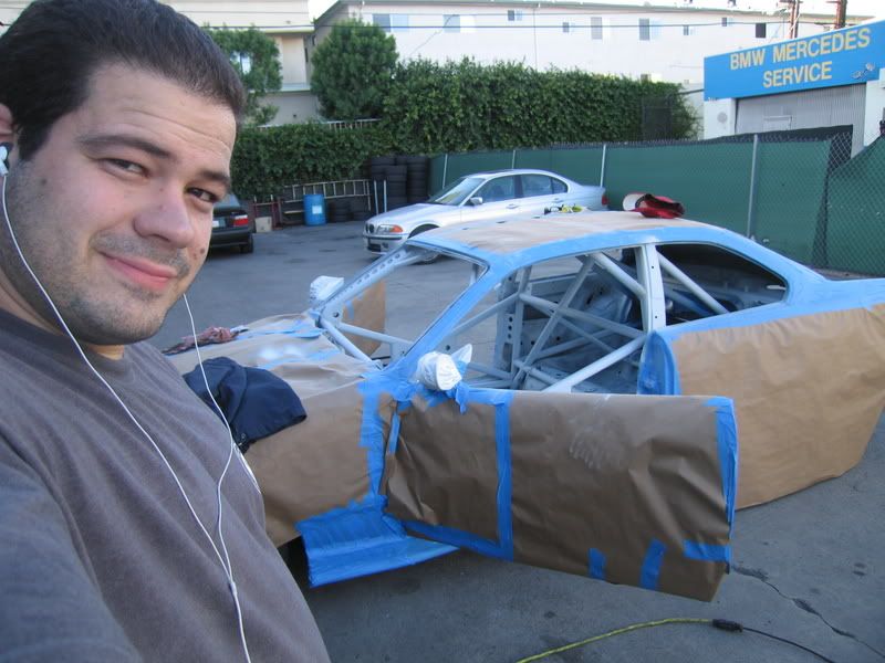
http://www.youtube.com/watch?v=vey-RcRPa5Q

We sprayed it avus blue like the car.....man painting a cage sucks!

We got the car all back together and it's almost ready for it's first test.

Now that we are finished with his car, he is going to help me with mine. Hopefully we can get my car done alot faster now!

I was able to resist the urge to attend the bmw wheel power meet then go to Long Beach grand prix and instead we worked on the car....

We broke out the sawzall and went nutz!!!

Started to prep the engine bay by removing radiator support/firewall sheet metal and the small firewall at the back of the engine bay thanks to a cool new spot weld drill bit and a nice big sawzall!

The radiator will be moved forward and lean a bit. the engine bay is now huge! You could fit a V8 in there! It will have a fan on the backside of it as well.

Began sanding/grinding down all the old crusty paint in the engine bay in prep for welding and fresh paint.

Removed dash support sheet metal as well. This was done as I will be adding a dash bar to connect to my engine bay tubes. I will be fabricating a new dash.

So basically the plan is that I will be adding to my cage alot.
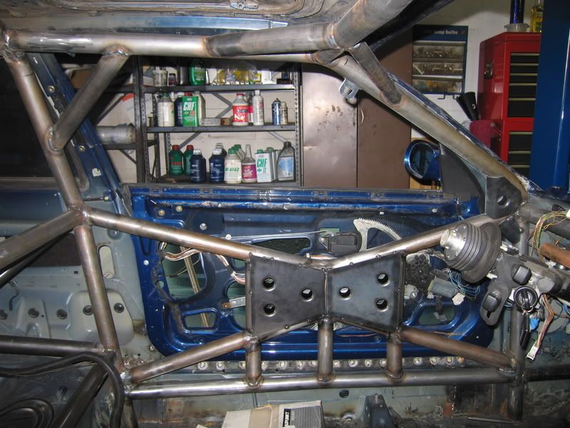
X on the door bars
Bars to tie into the rear subframe
rear strut towers tube and tubes to the diff mount
and finally extending the cage to the front shock towers

...also planed are Tilton pedal setup, mc with brake balance and bias control etc....

oh yeah rebuilding the engine! man...I think I bit off more than I can chew!

Hopefully my good friend Dimitri will lend me a hand and we can bust out all this incredible amount of work!

all the pics CLICK HERE.


I never did paint the engine bay.....

Actually I never touched the whole drive train and engine bay since I bought the car.

So I decided to tackle it all in what I'm calling "phase 2"

-painting engine bay
-reinforcing&restoring all suspension components
-more extensive cage layout
-fresh motor
-new braking "system"
-New and improved dash and wiring.


Thursday, March 13, 2008

SETUP FULL BLOG

My full setup blog,

I have one on the setup forums on the show's website......Click here.
or
you can see my reports with videos on my website HERE.