Showing posts with label fabrication. Show all posts

Sunday, June 22, 2008

Cage work finnaly begun!

Spent all day on Saturday working on my friends Dimitri's E36 race car assembling his new rear suspension setup. It was SOOO FREAKIN hot!!! Must of been like 110 at least! We got thru the day drinking lots of water and sweating about twice that and finished his car.

Started sunday by watching F1 with My mom and my stepdad. GO MASSA!! Go Senna!

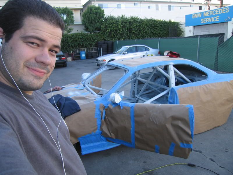
Then it was back to working the the OVEN they call the valley. Today we towed my car to the shop with Dimitri's X5. Which we like to call the ultimate tow vehicle! I wish it was mine.... the pair looks so good, don't they?

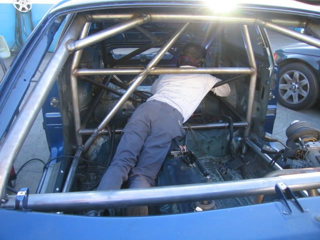
I decided to start work on the cage from back to front. That is to say I will start in the trunk and slowly work my way to the engine bay.

First order of business was to remove the awkward bar spanning across the 2 down tubes. I cut it out with the mighty sawzall then ground down the nub and painted it.

After grinding.....
after all painted up!
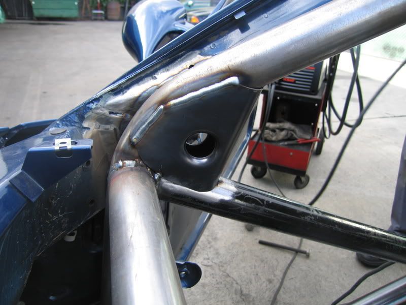
Next I used the same tube I just cut out to serve as my strut tube. You might ask me why no baseplate? Well I considered it, but as you might be able to see in the pictures the metal on that strut tower is VERY thick around 1/8". So I decided the best thing would be just to weld the tube directly on the strut tower. I will not be using coilovers so there really is not much load in this area. As my "downbar X" will be welded to my strut tube In case of a roll over the load will be shared by both mounting points. I did not design or install the original cage (ireland Eng. did) or else this whole area would of been very different. I'm just "modifing and adding" to the existing cage so keep that in mind.

Now after I welding in the "strut tower tube" I added the "diff tubes".

Quick flex test of this area I did today- I jacked the car up from the diff mount and I could actually see the floor board moving up or "bowing" from the center maybe 1-2mm at least. I was surprised by the amount of flex I observed! Now all the suspension forces that come thru the rear wheels make there way into the chassis thru the suspension arm into the subframe and into the car thru the subframe mounts. The other load path is thru the spring pads. The third and last location is the diff mount and the suspension loads and diff power "torquing" that might occur all transfer into this area.

TO address this I have seen this done many different ways. The diff mounts in 2 points on what basically is a square tube that spans in-between the strut towers along the floor. So the best solution would be to cut the tubing open (ala e36 subframe tie-ins) weld a plate then a tube sticking out. Then plate cloe the hole and weld you connecting tubes to it..... that's a bit too involved that I'm willing to go right now.

Another way I have seen is to tubes meeting in the middle of the trunk.....this seemed silly as the diff mounts in 2 spots and not is the center.

this pic from another 2002 race car build shows the diff mount and the tubing well.
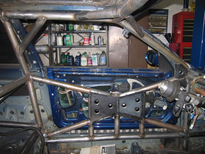
I decided to go with 2 tubes mounting to the area directly above the mounts. Pretty much like the pic above. Now I understand I'm not actually connecting the tubes directly to the diff mounts but the large plate and the 2 tubes will greatly increase the stiffness of the area and now any loads will be transfered up into the cage instead of bending the floor.....

There are 10,000 to cook potatoes...this is just how I cooked mine.
Also this leaves a nice space in the middle to mount the battery!
here you can see the diff mounting bolts in relation to the tubes. I used 1.5"x.120 wall DOM for the strut tube and 1 1/4"x.120 wall DOM for the diff tubes.
....and that's as far as we got in today slighty cooler 100+ degree heatwave......

Why do I wait till the summer to start working on things like these?

Wednesday, April 30, 2008

Paintball or work?


Took a break and went paint balling on Saturday but at least got some work in this weekend....

finished removing all the paint from both inside fenders....and welding all the small holes that were drilled to mount various items in the last 30 odd years of ownership.....
did some seam welding.... fender to firewall
I'm taking my inspiration for my "engine bay cage" from one of the cars from the guys from http://www.skidmarkracing.net

here is his tube design/engine bay

Here is my version of his concept....Im calling this Version 1.0

I did not like the way he just "seamwelded" the tubing to the 'shock tower'. I thought I could improve on his idea. This is and old car running really STIFF springs supported by 39 year old spot welds and rusty sheetmetal.

So I decided to construct a 'strut tower' reinforcement box.

Both to strengthen the strut mounting area and to transfer some of the load into the roll cage.

My racing rules state I cannot alter the suspension mounting points. There fore my strut holes are in the same place and I'm not moving the strut mounting point inward like I would like to (to gain more camber). I also would like to raise the strut tower abit to gain suspension travel. But that is also prohibited.

So it is merely a mounting point for the tubes and a reinforcement for the area.came up with this strut tower reinforcement "box"
more detailed view of the reinforcement box/tube mounting... the black circle represents where the tube will be welded to the 'box'
A side view of the design. The most forward tube will reach down and be welded to the frame rail. The 2 triangulated tubes will reach thru the dash and attach to the top dash tube.
I will also weld a "taco gusset" with a nice dimple die to this connection.

Monday, April 21, 2008

Cage modifications started!

We finally finished my friend Dimitri's '95 M3 NASA TT car. We put quite an extensive cage in it. I think he will put up a Project thread here in a few days.

here's a few pics!


here a video of the completed car...
http://www.youtube.com/watch?v=vey-RcRPa5Q

We sprayed it avus blue like the car.....man painting a cage sucks!

We got the car all back together and it's almost ready for it's first test.

Now that we are finished with his car, he is going to help me with mine. Hopefully we can get my car done alot faster now!

I was able to resist the urge to attend the bmw wheel power meet then go to Long Beach grand prix and instead we worked on the car....

We broke out the sawzall and went nutz!!!

Started to prep the engine bay by removing radiator support/firewall sheet metal and the small firewall at the back of the engine bay thanks to a cool new spot weld drill bit and a nice big sawzall!

The radiator will be moved forward and lean a bit. the engine bay is now huge! You could fit a V8 in there! It will have a fan on the backside of it as well.

Began sanding/grinding down all the old crusty paint in the engine bay in prep for welding and fresh paint.

Removed dash support sheet metal as well. This was done as I will be adding a dash bar to connect to my engine bay tubes. I will be fabricating a new dash.

So basically the plan is that I will be adding to my cage alot.

X on the door bars
Bars to tie into the rear subframe
rear strut towers tube and tubes to the diff mount
and finally extending the cage to the front shock towers

...also planed are Tilton pedal setup, mc with brake balance and bias control etc....

oh yeah rebuilding the engine! man...I think I bit off more than I can chew!

Hopefully my good friend Dimitri will lend me a hand and we can bust out all this incredible amount of work!

all the pics CLICK HERE.


I never did paint the engine bay.....

Actually I never touched the whole drive train and engine bay since I bought the car.

So I decided to tackle it all in what I'm calling "phase 2"

-painting engine bay
-reinforcing&restoring all suspension components
-more extensive cage layout
-fresh motor
-new braking "system"
-New and improved dash and wiring.


Saturday, January 12, 2008

Rear trailing arm reinforcements!

Next up : Reinforcing the rear trailing arms.

Now unless you can find yourself a nice new set of boxed Tii arms you'll have to "box" your trailing arms yourself. I seen many other people doing it many ways....I think my design is pretty sweet. and STRONG.

Initially I was going to add an additional bar across the arms but I really do not think it is necessary.

One of the dimple hole line up with the brake line holes for installation.

Once again fixturing/jigging is the name of the game here. The last thing you want is bent reinforced arms that are useless. Welding tends to warp/shrink everything. I found that I actually had to preload or stretch the arms apart so that when I was done I would had the same measurements.

This whole process takes alot of work!!

Remove arms
disassemble arms
sandblast arms
paint arms on the inside
clean arms for welding (grinding)
make template from cardboard
cut gussets from sheet metal
dimple sheet metal
bend/form gusset to control arm curve
secure in place for tack welding
measuring
applying "jig"
measuring
welding reinforcements
Cleanup
Painting

finally re installation!!

wow...trust me it takes alot more time and work to do it than to write this post!

I know what some race shops charge to do this and now I know why.

That said I made 2 pairs and 1 pair is for sale. I will be making more as well and selling them on my site. If your interested in a set email me.

once again if your going to do this yourself be very careful not to end up with bent arms!!!!

see all the pics CLICK HERE.


forming and bending it so that it would fit perfectly flush took alot of time. Alot of back and forth!


I used a punch and dimple "Dimple die" tool I bought from www.tricktools.com. I bought a 1/2 inch press model $40 and a bigger punch model that I used for the trailing arms....$90+

They have many a few different types. I bought the one that after drilling a pilot hole you bolt the two halves together and by using a air gun as it brings the two halves together it also punches the hole! You can also and preferable do this using a Press. You keep pressing the Die together until your gusset is nice and flat again. If you do it correctly you should end up with a nice flat gusset with dimples on it.

I used 16gauge sheet metal.


Wednesday, June 21, 2006

cage tie-ins ...

More work today......

I'm currently attaching the roll cage to various points on the unibody.

VARA allows this in my class C-Sedan, although in BMW CCA doing this to my cage moved me up from "prepared" class to "modified" class. I would never be competitive in mod. class. But I only plan on racing with VARA so.....

the seam welding and these "ties" will considerable help with the overall torsional rigidity of the chassis.........I hope!

I needed some practice with the TIG anyways.....

I do have to say welding "out of position" is extremely challenging.... this time I was hanging over the door bars essentially looking upside down at the project and welding on a vertical surface!!

a torch operated control would be preferable in these extreme out of position TIG welds. It becomes a challenge to operate the foot control in some positions....

even so........my welds were acceptable. I know they might not look great, but I am confident I got good penetration.

I learned some things doing the right side, now on the other side I hope to see better welds!

after adding a couple more tubes on the cage, I'll be ready for BONDO! then primer.....


my acceptable TIG welds...
did some of the overhead tabs today along the roofline....

not sure how much difference this all going to make but hey I felt like welding something!